Chart Recorder
A Chart Recorder is a data logging instrument which takes the readings from various data capturing Screen Objects such as a Data Window, Level Gauge, Dial Gauge, Meter Gauge, or Signal Lamp, and plots it on a grid divided graph much like a conventional paper strip chart recorder. The number of horizontal and vertical grid lines are user defined, as well as the position and magnitude of each individual data field being plotted. It can be used to draw the plot lines live as the data is being accumulated, or scroll back and view different portions of the graph at various positions over time.
Once a Chart Recorder is placed on the screen it can be selected by clicking on it with the left mouse button. To move the object, place the cursor over it, hold down the left mouse button and drag the object to the desired position. Resize handles are provided to allow adjustment of the overall size by dragging on them with the mouse in a similar fashion.
To set the properties of a Chart Recorder, right-click on the object or select "Properties" in the <Edit> menu while the Chart Recorder is selected. The following is a summery of the user defined attributes in the Properties dialog box.
Properties Dialog Box:
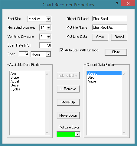
Font Size: Selects the font size used for the text characters in the Chart Recorder as well as the overall size of the various components such as the buttons and data windows.
Horiz Grid Divisions: Selects the number of horizontal grid divisions that will be used on the plot-line graph. The width of the graph will be divided up by this number using dotted lines.
Vert Grid Divisions: Selects the number of vertical grid divisions that will be used on the plot-line graph. The height of the graph will be divided up by this number using dotted lines.
Scan Rate: Selects the time interval between each scan that is used to capture data from the Screen Objects and plot it on the Chart Recorder graph. A fast scan rate provides more plot-line resolution but uses up more of the operating system's memory and creates a larger file if saving the plot to disk.
Span: Selects the total recording time span of the plot-line history which will be held in memory at any given time. When this time span fills up, the oldest plot-line data will be written over as new data is scanned and plotted, much like a continuous loop tape recording machine. A large recording span will hold more plot-line history but will use up more of the operating system's memory and will create a larger file if saving the plot to disk.
Object ID Label: Type in a label that will be used for identification by other objects within ModCom when sending instructions to the Chart Recorder.
Plot File Name: Type in the name of the file which can be used to save the plot-line data to after the Chart Recorder has completed a run session. If the drive and directory is omitted, the file will be placed in the same drive and directory in which ModCom is currently working. Note, this entry box supports variables.
Save: By clicking on this button, the Chart Recorder's current plot-line data will be written to the file listed above. Keep in mind that each time the Chart Recorder is started, any old data held in memory will be cleared. So it is important to save this data ahead of time if there may be a reason to go back and view it.
Recall: Click on this button to recall the plot-line data which was saved at an earlier time. The contents of the file listed above will be loaded into the Chart Recorder's memory including the data field selection and order. The "Auto Start with run loop" box will automatically be unchecked so that when the run-loop is started, this data will not be cleared and instead be viewed on the Chart Recorder's graph.
Auto Start with run loop: Check this box to have the Chart Recorder automatically begin running as soon as the run-loop is started. If this box is unchecked, the Chart Recorder will not begin running until a Start Chart Recorder function is executed. Note, when a Chart Recorder starts running, it begins by clearing any old data from the plot-line memory and then it continuously scans the Screen Objects and plots their data on the Chart Recorder graph until the run-loop is halted or a Halt Chart Recorder function is executed. Once halted, the plot-line data will remain in memory until the next time it is started. This allows the operator to scroll back and forth and view the plot-line data captured at the previous operation, or stop the run loop and save the plot-line data to file.
Available Data Fields: This box contains a list of all Screen Objects available in the current project which are capable of being used to create a plot-line on the Chart Recorder graph, but have not yet been selected to do so.
Current Data Fields: This box contains a list of all Screen Objects which have been selected to have their data plotted on the Chart Recorder graph. The data field order from top to bottom denotes the order in which the field boxes are shown at the right side of the Chart Recorder's main frame.
Add to List: To use this option, a data field must first be selected from the "Available Data Fields" list at the left. Click on this button to add the selected data field to the list of fields to be plotted on the Chart Recorder graph. This data field will then be removed from the list at the left and placed in the list at the right.
Remove: To use this option, a data field must first be selected from the "Current Data Fields" list at the right. Click on this button to remove the selected data field from the list of fields to be plotted on the Chart Recorder graph. This data field will then be removed from the list at the right and placed in the list at the left. Note, if the Screen Object associated with this data field no longer exists, the data field will not be placed at the left.
Move Up: To use this option, a data field must first be selected from the "Current Data Fields" list at the right. Click on this button to move the selected data field one place up in the listing order, which in turn, denotes the order (top to bottom) that the field boxes are shown on the Chart Recorder's main frame.
Move Down: To use this option, a data field must first be selected from the "Current Data Fields" list at the right. Click on this button to move the selected data field one place down in the listing order, which in turn, denotes the order (top to bottom) that the field boxes are shown on the Chart Recorder's main frame.
Plot Line Color: To use this option, a data field must first be selected from the "Current Data Fields" list at the right. Click on this box and a drop-down menu will appear showing the color choices available to represent the plot line associated with the data field. This color will also be used for the title of its field box which is shown at the right side of the Chart Recorder's main frame.
Operation:
While the main run-loop is executing, the Chart Recorder can be operated on by the user by clicking on the various buttons at the bottom and right hand side of the Chart Recorder's main frame. Below is a summery of the operation of each button and the definition of the various numerical fields shown on the Chart Recorder's main frame.
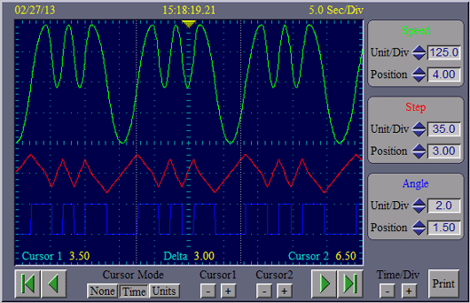
Numerical Fields (top of frame):
Date Field: This field is located above the top left corner of the Chart Recorder's plot-line graph and shows the date that the currently viewed data was captured. If the graph is scrolled left or right, the date will update accordingly if necessary. Note, both the "Date" and "Time" fields will always reflect the date and time of the center of the plot-line graph where the yellow arrow is shown.
Time Field: This field is located above the center of the Chart Recorder's plot-line graph and shows the time that the currently viewed data was captured. If the graph is scrolled left or right, or if the plotting of new data forces the graph to scroll, this time will update accordingly. Note, both the "Date" and "Time" fields will always reflect the date and time of the center of the plot-line graph where the yellow arrow is shown.
Sec/Div Field: This field is located above the top right corner of the Chart Recorder's plot-line graph and shows the number of seconds per division that the width of the graph is divided into.
Main Buttons (bottom of frame):
Scroll to Start: This button is located below the bottom left corner of the Chart Recorder's plot-line graph and is shown as a green left pointing arrow with a vertical line at the left side of it. Clicking on this button will move the plot viewing window to the beginning of the Chart Recorder's recording span. The date and time fields at the top of the Chart Recorder's main frame will be updated accordingly. See "Scrolling tips" below.
Scroll Left: This button is located below the bottom left corner of the Chart Recorder's plot-line graph just to the right of the "Scroll to Start" button and is shown as a green left pointing arrow. Clicking on this button will scroll the plot viewing window towards the left (earlier in time). The date and time fields at the top of the Chart Recorder's main frame will be updated accordingly. Holding this button down will scroll continuously at an increasing rate. See "Scrolling tips" below.
Scroll to End: This button is located below the bottom right corner of the Chart Recorder's plot-line graph and is shown as a green right pointing arrow with a vertical line at the right side of it. Clicking on this button will move the plot viewing window to the end of the Chart Recorder's recording span which is where the live data is being plotted. The date and time fields at the top of the Chart Recorder's main frame will be updated accordingly. See "Scrolling tips" below.
Scroll Right: This button is located below the bottom right corner of the Chart Recorder's plot-line graph just to the left of the "Scroll to end" button and is shown as a green right pointing arrow. Clicking on this button will scroll the plot viewing window towards the right (later in time). The date and time fields at the top of the Chart Recorder's main frame will be updated accordingly. Holding this button down will scroll continuously at an increasing rate. See "Scrolling tips" below.
Cursor Mode: This 3-position button sets the mode of the cursors which can be used to measure the distance between points of interest on the plot line graph. If set for "Time", two vertical lines are shown which can be moved to different positions in time. If set for "Units", two horizontal lines are shown which can be moved to different positions in units of amplitude. In either case, numerical fields at the bottom of the Chart Recorder's plot-line graph will show the current position of each cursor as well as the distance between them.
Cursor1 Buttons: These buttons, labeled positive and negative, are used to move the position of cursor 1. Positive moves towards the right or top. Negative moves towards the left or bottom.
Cursor2 Buttons: These buttons, labeled positive and negative, are used to move the position of cursor 2. Positive moves towards the right or top. Negative moves towards the left or bottom.
Time/Div Buttons: These buttons, labeled positive and negative, are used to adjust the time per division settings for the Chart Recorder's plot-line graph. Decreasing the time per division, in effect, zooms in on the plot-line graph. Increasing the time per division does just the opposite. Note that if you increase the time per division to a great extent, it slows down the scrolling operation. This is because as the time per division increases, the screen covers a much larger section of the plot-line history, and in order to redraw the graph after each scrolling movement, more data has to be loaded from memory and plotted on the screen.
Print Button: Click on this button to print the portion of the plot-line graph which is currently being viewed on the Chart Recorder's screen. The plot-line accuracy or resolution is not dependent or bound by the video display resolution. So for instance, if the printer has a much higher resolution than the video display, this higher resolution will be used to plot the data points which are printed on the paper providing a much smoother and accurate graph than what is seen on the video screen.
Screen Object Field Boxes (right side of frame):
Once you've selected Screen Objects to be plotted on the Chart Recorder's graph, a field box for each object will be shown at the right side of the Chart Recorder's main frame. Below is a summery of the various numerical fields and buttons common to each of the Screen Object's field box.
Title: The top of each field box will show the Screen Object's title which is the object ID label defined in the Screen Object's properties dialog box. This title will be drawn in the same color that will be used to draw its plot line.
Unit/Div: This numerical field shows the number of units per division that the Screen Object's value will be represented in when plotted on the graph. Use the two buttons shown as blue arrows to make adjustments to this setting. A unit is equal to one whole number in the format being used by the Screen Object. If the Screen Object is a Signal Lamp, it will equal 1 when it is turned on, and 0 when it is turned off. If the Screen Object is an Event Timer, one unit will equal 1 second regardless of how many digits are shown to the right of the decimal point, or even if the time value is displayed with only the hours and minutes, omitting the seconds.
Position: This numerical field shows the vertical position of the Screen Object's plot line when the Screen Object's value is equal to zero. Use the two buttons shown as blue arrows to make adjustments to this setting. This feature can be used to separate the plot lines of the different fields when multiple fields are being plotted on the graph.
Scrolling Tips:
When a Chart Recorder is capturing live data, the plot lines will grow towards the right as new data is being captured and plotted on the screen. If the user clicks on one of the scroll buttons, the plot-line graph will freeze at the current moment in time. All the data from the Screen Objects is still being scanned and stored in memory as expected, but it is no longer being added to the right side of the plot lines on the graph. This condition will stay in effect until exiting the scroll mode by clicking on the "Scroll to End" button. However, if scrolling towards the right (later in time) and reaching the end of the plot lines, each additional click of the "Scroll to Right" button (or if holding the button down) will force the Chart Recorder to redraw the graph. And since it is still capturing new data continuously, the plot lines will grow accordingly and move towards the right.
This effect can also be seen if the "Recording Span" has been filled up, and the user scrolls in the opposite direction all the way to the start of the plot lines. In this case, because the "Recording Span" is full, as new data is captured the old data (at the start) is truncated. And so if clicking on the "Scroll to Left" button or "Scroll to Start" button while at the start of the plot lines, the graph will be redrawn omitting those portions of the left side of the plot lines which have been truncated. This will cause the plot lines to move to the left.
Disruption in Plot Lines:
While the Chart Recorder is running, it is continuously capturing data at the current Scan Rate and storing this data in memory to be used to plot the graph. Unfortunately, the faster the Scan Rate, the more dependant the Chart Recorder is on maintaining priority over the Windows operating system. If the operating system is called on to perform other tasks, such as opening another program, processing user input, performing a printing operation, etc., it will not be able to keep up with the Chart Recorder's demand to capture data, especially if it is set to a fast Scan Rate. This does not harm anything, however it does produce gaps in the continuous stream of data being stored in memory by the Chart Recorder. And these gaps will appear as a disruption in the smooth flow of the plot line shown on the Chart Recorder's graph.
While a Chart Recorder is capturing data, it is best to limit the amount of time that the Windows operating system is taken away from ModCom to perform other tasks. Close all other programs and avoid user input outside the ModCom window. User input inside the ModCom window such as pressing a Push Button, operating a Slider Control, etc., will not cause as much of a disruption in the plot line data because most operations within ModCom are designed to be interleaved around each other. Also, placing a Chart Recorder on a separate page that is not being viewed at all times relieves Windows from having to constantly redraw the plot line and use up valuable processor time. Capturing data from the Screen Objects and writing it to memory is very fast, but constantly redrawing the plot line takes a significant amount of time.
Recalling Plot Data:
When recalling the plot line data from an existing file, keep in mind that the only thing stored in the file is the name of each Screen Object and the plot line data associated with it. Any Chart Recorder settings or attributes are not stored in the file. So for instance, placing a blank Chart Recorder on the screen and recalling the plot line data that was previously recorded by a different Chart Recorder, will not automatically set the Units/Div, Position, and plot line colors that was used by the original Chart Recorder. These settings will have to be adjusted manually.
Using Log File Data:
Because the data format used by a Chart Recorder is the same as the format used by a normal Data Logging operation, it is perfectly legal to load a ModCom generated log file into the Chart Recorder memory. However, in order to be loaded by a Chart Recorder, the first two fields in the log file must be the date and time, in that order. If not, the Chart Recorder will not accept the file. So when setting up a Data Logging operation, it is good practice to always place the date and time fields up at the top of the list of "Current Data Fields" shown in the Data Logging properties dialog box. That way, if desired at some point in the future, the log file has the capability of being viewed on a Chart Recorder's graph.
|