|
ERROR!
You must enable Java Script on your browser to navigate this site. |
||||||||
|
Isolated Stackable DAQ
|
 |
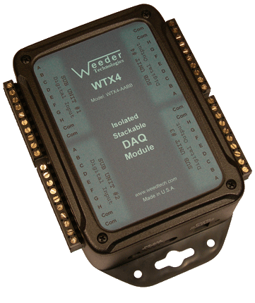
Isolated DAQ Module WTX4 Up to 16 differential input channels programmable to read voltages and convert them to direct engineering units of choice. |
 |
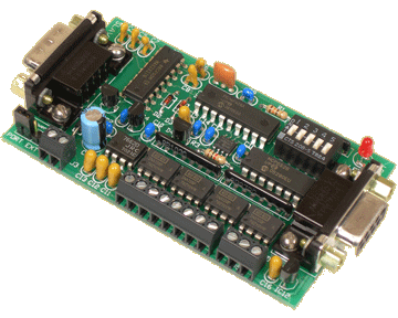
Analog Input Card 4 differential input channels programmable to read voltages and convert them to direct engineering units of choice. |
Analog Input Definition
The acquiring and processing of data using a computer is a vital requirement of any industrial process or control operation. However, a computer only recognizes binary digital numbers and most sensors that acquire data by converting physical characteristics such as temperature, pressure, load, weight, etc. into an electrical signal, do so in an analog nature. In other words, the output of the sensor is some form of voltage or current which is not suitable for a computer to input or process. An analog input circuit, or A to D converter, is needed to change these analog voltages to a digital stream which can then be transferred into a computer via the communications port such as USB or RS232. The Analog Input modules shown here have all the necessary A/D circuitry for signal conversions including many advanced features not seen in most DAQ products on the market. For instance, the calibration of the voltage gain and offset is user programmable so that the output can be scaled to match the sensor and the type of information that the sensor is meant to represent.
Stackable Capability
Stackable refers to the ability to connect multiple units together and share a single communications port of a host PC, laptop, or Single Board Computer (SBC). The DAQ modules are offered in two different footprints as shown above, enclosed in a case with full electrical isolation, or a
Host Communications
To communicate with the DAQ modules, commands are sent to the individual units by including a header character at the beginning (the address) so that it can be routed to the appropriate unit. If using multiple units connected together, the DIP switch for each unit should be set to a different position so that it will be assigned a different header character. Each DAQ module has its own command set used to configure it, operate the functions, and to read data from it. These commands are listed in the product data sheets. A typical command string looks like this:
HCNV{cr}
H = Header Character
C = Command Character
N = Channel Number (if applicable)
V = Value (if applicable)
{cr} = Carriage Return
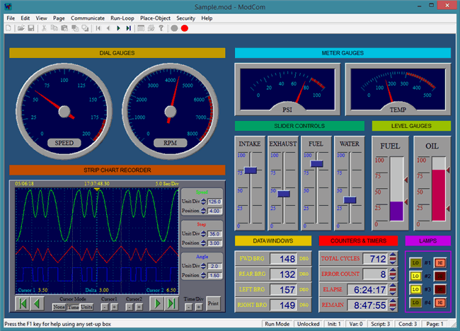
If using our ModCom HMI software, the carriage return is not necessary because ModCom automatically inserts this at the end of each command string. ModCom has a communications dialog box which can be used to transmit individual commands to the DAQ modules and see the data coming back. This is helpful in learning the style of the
Calibration Mode & Range
Each of the analog input channels of the DAQ modules shown above can be set up to use 1 of 5 different calibration modes and input voltage ranges. For each input channel there are three factory calibrated modes which will return the results listed in voltage, and two user programmable custom modes which will return the results listed in any direct linear engineering units of choice. To calibrate a custom mode, first set the zero point, then either apply a known stimulus and tell the module what number you want to see on the computer screen, or tell the module what exact voltage you want to represent one unit of measurement. The gain and offset for this particular input channel will be automatically
Input Channel Scanning
During normal operation, the Analog Input module continuously scans all channels in the background regardless of whether or not they are being polled by the host. The full
User Programmable Modes
The Analog Input modules incorporate a
SPAN can be used if a known output reading can be generated by the sensor. Sensor manufacturers often include a shunt resistor for this purpose and when attached to the sensor's bridge, will cause it to output a voltage which represents a specific reading. Applying a known load or stimulus to a sensor also works well. After setting up the sensor so that it outputs the known reading, transmit the SPAN command with the value field containing the reading that should be displayed on the computer screen. Multiplying the value by multiples of 10 will increase the resolution. For example, if applying a
FACTOR can be used if the actual voltage that equals one unit of measurement can be determined. To calculate this voltage in mV, use the factory listed output of the bridge sensor in the following equation:
value = Out * E / FS where:
Out = Output of the sensor in mV/V.
E = Excitation voltage applied to bridge.
FS = Full scale capacity of the sensor.
For best results, the excitation voltage should be measured directly at the bridge using the same analog input channel and lead wires that will be attached to the bridge output itself. Transmit the FACTOR command with the value field containing the results of this equation. Dividing the value by multiples of 10 will increase the resolution displayed on the computer screen in the same way as multiplying the value used in the SPAN command, as discussed earlier. The FACTOR command can also be used to set the display resolution so that it equals
Input Voltage Range
Each of the input channels of the Analog Input module has a common mode range of ▒10V regardless of the MODE it is set to or the magnitude of the differential voltage it is measuring. Both positive and negative inputs must remain inside this range at all times or conversion errors will result. If connecting to a bridge sensor for instance, the excitation voltage applied to the bridge must be less than 20V in order to keep the inputs within this common mode range. An excitation of 5V to 15V is recommended for proper operation.
4-20 mA Current Transmitters
To read the data from a
