|
ERROR!
You must enable Java Script on your browser to navigate this site. |
||||||||||||
|
Isolated Stackable DAQ
|
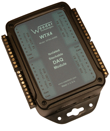 |
Isolated DAQ Module WTX4 Up to 16 high speed input channel pairs which can track the position of 16 quadrature encoders simultaneously, and store a count value up to 16,777,215 each with user programmable rollover limits. Can also include a combination of other I/O types. read more... |
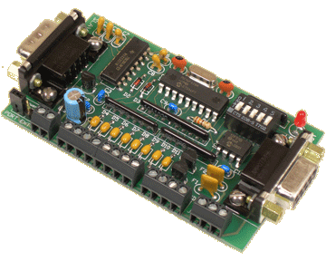 |
Digital Input Card 4 high speed input channel pairs which can track the position of 4 quadrature encoders simultaneously, and store a count value up to 16,777,215 each. Also includes 2 digital output channels. read more... |
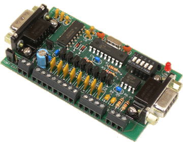 |
Digital Output Card 1 high speed input channel pair that can track the position of a quadrature encoder and store a count value up to 16,777,215. Also includes 8 digital output channels. read more... |
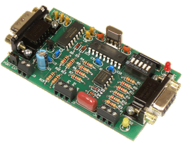 |
Pulse Counter/Timer Card 1 high speed input channel pair that can track the position of a quadrature encoder and store a count value up to 16,777,215. Can also read Frequency, Period, or Duty Cycle. read more... |
Incremental Encoder Definition
An incremental or quadrature encoder, which is sometimes called a position encoder or absolute encoder, is a special kind of sensor which is designed to measure both the amount and direction of movement. This could be a shaft as it rotates for instance, or some kind of structure which uses a rotating shaft for positioning. The encoder has two separate output signals which are 90° out of phase and this phase relationship is what makes it possible to determine the direction of rotation. The DAQ modules listed above incorporate circuitry to monitor these two signals and automatically track the position by incrementing or decrementing an internal counter depending on the direction of travel. A host computer can then poll the DAQ module and retrieve the current position at any time, whether its moving or at rest. In addition, multiple channels on the same unit can be decoding separate signals simultaneously without interference with each other.
Stackable Capability
Stackable refers to the ability to connect multiple units together and share a single communications port of a host PC, laptop, or Single Board Computer (SBC). The DAQ modules are offered in two different footprints as shown above, enclosed in a case with full electrical isolation, or a
Host Communications
To communicate with the DAQ modules, commands are sent to the individual units by including a header character at the beginning (the address) so that it can be routed to the appropriate unit. If using multiple units connected together, the DIP switch for each unit should be set to a different position so that it will be assigned a different header character. Each DAQ module has its own command set used to configure it, operate the functions, and to read data from it. These commands are listed in the product data sheets. A typical command string looks like this:
HCNV{cr}
H = Header Character
C = Command Character
N = Channel Number (if applicable)
V = Value (if applicable)
{cr} = Carriage Return
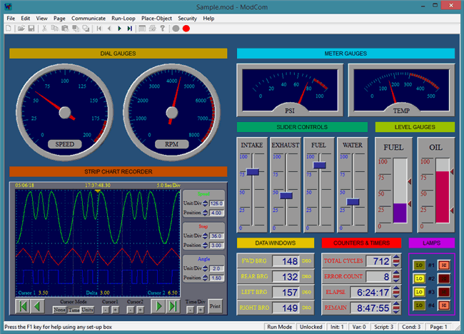
If using our ModCom HMI software, the carriage return is not necessary because ModCom automatically inserts this at the end of each command string. ModCom has a communications dialog box which can be used to transmit individual commands to the DAQ modules and see the data coming back. This is helpful in learning the style of the
Input Types
The input channels of the Digital Input modules can be connected to TTL level outputs, dry contacts of switches, optical sensors, proximity sensors, or quadrature encoders which are sometimes called incremental encoders or rotary encoders. The WTX4 series also incorporates a user programmable
Input Protection
In many cases, the industrial environment is a very harsh and unforgiving opponent to a typical digital input sensing circuit. A large machine or motor that switches on and off will inadvertently induce voltage spikes onto any neighboring electrical wires even if it is not physically touching them. And if these wires are attached to sensitive electronics, damage could result. Fortunately, the digital inputs of the WTX4, WTDIN-M, and WTDOT-M series incorporate high voltage transient protection to insure that these voltage spikes do not cause any harm. In addition, the inputs are configured to accept a wide range of input voltages that represent each logic level. A logic high can be anywhere from +4V up to +40V, a logic low can be anywhere from +0.8V down to -40V. This allows for the connection to sensors with very diverse output voltages.
Switch Contact Debounce
A typical switch or button uses metal plates (called contacts) which can be moved together or apart in order to make or break the current path. During switch closure, when these plates first make contact with each other, they will bounce several times before coming to rest. This bouncing of the contacts will appear as multiple transitions to a digital input monitoring system, and in most cases, not be desirable.
Each of the input channels of the Digital Input modules incorporates its own
Polling or Auto Reporting
The logic state of each input channel can be read (or polled) by the host using the READ command, or each channel can be set up to automatically report a logic transition by using the SWITCH or BUTTON command. This automatic reporting allows the host to be performing other tasks or transmitting other commands while it is waiting for an external mechanical switch or button to change state.
Pulse Counting Function
The digital inputs can be set up to count pulses using the COUNT command. The WTX4 series also includes a feature allowing the user to choose whether to increment or decrement the
Quadrature Encoder Function
A normal inductive pickup, optical sensor, or proximity sensor attached to a rotating shaft can keep track of the pulse count and/or RPM frequency but it can not determine the direction that the shaft is rotating. An incremental or rotary encoder with a quadrature output incorporates two individual signals which are 90° out of phase. These
RPM Scanning Function
The input channels can also be set up to measure the rate of a rotating shaft by using the TACHOMETER command. Once this command is issued on a particular input channel, the pulse rate of the applied signal will be continuously sampled in the background, converted to RPM, and stored in memory. Each time that the TACHOMETER command is issued, the latest results will be returned to the host without any acquisition delay. However, although the results returned to the host will always be immediate, the update rate may be much slower depending on the frequency of the input signal. The lower the RPM, the more time it takes to sample and get an accurate reading. And since the Digital Input module can only sample one input channel at a time, a low RPM signal applied to one channel will slow down the update rate of any other channels of this sub unit which are configured to read RPM.
