 |
| |||||||||||||||||||||||||
  Weeder Technologies 90-A Beal Pkwy NW Ft Walton Beach FL 32548 850-863-5723 info@weedtech.com ESTABLISHED: 1989 DUNS: 969723154 CAGE CODE: 4T5L9 |
Isolated Stackable DAQ
|
|||||||||||||||||||||||||
 |
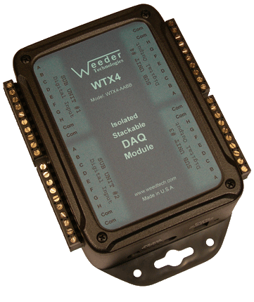
Isolated DAQ Module WTX4 Up to 16 differential input channels that accept types J, K, T, E ungrouded thermocouples and read temperature in Fahrenheit or Celsius. Inputs protected to ±40 volts. Can also include a combination of other I/O types. read more... |
 |
Thermocouple Input Card 4 differential input channels that accept types J, K, T, E ungrouded thermocouples and read temperature in Fahrenheit or Celsius. Inputs protected to ±40 volts. read more... |
Thermocouple Definition
A thermocouple is constructed of two wires made out of dissimilar metals that are bonded together on one end with a welded bead, and left open on the other end. If there is a temperature difference between the welded end and the open end, a voltage will appear across the wires at the open end and this voltage can be measured to calculate the temperature of the welded bead. But this does not mean that a thermocouple measures absolute temperature, it does not. It only measures the "difference" in temperature between one end of the wire and the other. If the temperature at the open end of the wire is unknown, it is impossible to determine the temperature at the welded bead. The DAQ modules listed above have an
Another problem which arises when using thermocouples to measure temperature is that the voltage to temperature relationship is
Stackable Capability
Stackable refers to the ability to connect multiple units together and share a single communications port of a host PC, laptop, or Single Board Computer (SBC). The communications bus uses a stratagem based on the Carrier Sense Multiple Access (CSMA/CD) protocol. Carrier Sense (CS) is the monitoring of the data bus for a period of inactivity before a DAQ module is allowed to begin its own transmission. Multiple Access (MA) means that once the bus is free, every DAQ module in the network has an equal opportunity to transmit a frame. And Collision Detection (CD) uses non destructive bit wise arbitration to preserve the integrity of a data frame when two or more DAQ modules try to transmit at the exact same time. And since the data frame that wins arbitration remains intact during a collision, there is no additional communications delay when a collision occurs no matter how often it happens.
Host Communications
To communicate with the DAQ modules, commands are sent to the individual units by including a header character at the beginning (the address) so that it can be routed to the appropriate unit. If using multiple units connected together, the DIP switch for each unit should be set to a different position so that it will be assigned a different header character. Each DAQ module has its own command set used to configure it, operate the functions, and to read data from it. These commands are listed in the product data sheets. A typical command string looks like this:
HCNV{cr}
H = Header Character
C = Command Character
N = Channel Number (if applicable)
V = Value (if applicable)
{cr} = Carriage Return
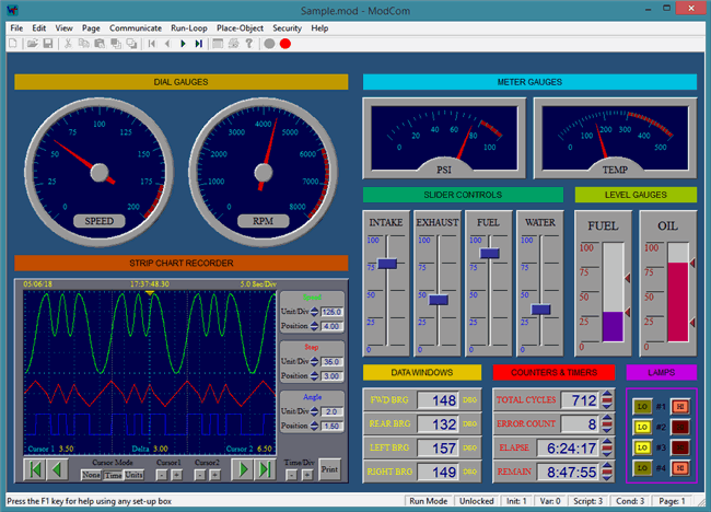
If using our ModCom HMI software, the carriage return is not necessary because ModCom automatically inserts this at the end of each command string. ModCom has a communications dialog box which can be used to transmit individual commands to the DAQ modules and see the data coming back. This is helpful in learning the style of the
Thermocouple Temperature Range
The range of temperatures which can be measured by the Thermocouple Input sub unit and its thermocouple sensors is dependant on two factors, the physical limitations of the thermocouple itself, and the mathematical boundaries inherent to the polynomial equation that is used to calculate the temperature. The former specifications can be obtained from the thermocouple manufacturer and will vary depending on the form of weld used to make the junction, and the type of insulating material used to cover the wires. As for the limits of the polynomial equation used for temperature conversions, refer to the table shown below.
| Thermocouple Temperature Range | ||
|---|---|---|
| Type | Celsius | Fahrenheit |
| J | -210° to +1200° | -346° to +2192° |
| K | -200° to +1372° | -328° to +2502° |
| T | -200° to +400° | -328° to +752° |
| E | -200° to +1000° | -328° to +1832° |
Thermocouple Grounding
Thermocouples are offered in a choice of configurations, "grounded", "ungrounded", or "exposed" junctions. If using “grounded” thermocouples, or “exposed” thermocouples which are touching ground, be sure to separate them on different WTX4 sub units if the grounds they are attached to come from different sources with different voltage potentials. Using “ungrounded” thermocouples is the preferred choice because they can all share the same sub unit without causing grounding conflicts with each other.

