 |
| ||||||||
  Weeder Technologies 90-A Beal Pkwy NW Ft Walton Beach FL 32548 850-863-5723 info@weedtech.com ESTABLISHED: 1989 DUNS: 969723154 CAGE CODE: 4T5L9 |
Isolated Stackable DAQ
|
 |
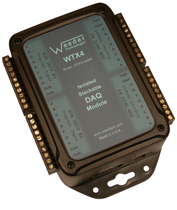
Isolated DAQ Module WTX4 Up to 16 analog output channels which can span from -10.00 to +10.00 VDC using 0.01 volt resolution. Built in S-Curve and Trapezoidal ramp generator with emergency stop switch input. Can also include a combination of other I/O types. read more... |
 |
Analog Output Module 4 analog output channels which can span from -10.00 to +10.00 VDC using 0.01 volt resolution. Built in S-Curve and Trapezoidal ramp generator with Pause switch input. read more... |
Analog Output Definition
Controlling machinery using a computer is a vital requirement of any industrial process or control operation. Many machines such as motor speed controllers, hydraulic presses, flow valves and actuators, accept a DC control signal to vary its output. However, a computer only has the ability to output binary digital numbers via the USB or RS232 port, not a variable DC voltage. An analog output circuit, or D to A converter (DAC), is needed to change the digital stream coming from a computer's output port to an analog voltage which can then be used to control the machinery. The Analog Output modules shown here have all the necessary D/A circuitry for this conversion including many advanced features not seen in most DAQ products on the market.
Stackable Capability
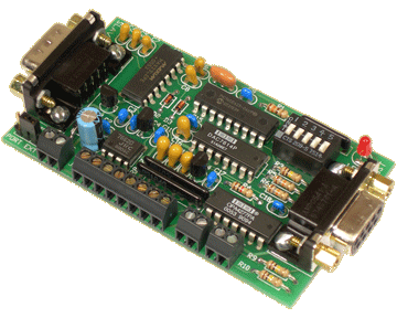
Stackable refers to the ability to connect multiple units together and share a single communications port of a host PC, laptop, or Single Board Computer (SBC). The DAQ modules are offered in two different footprints as shown above, enclosed in a case with full electrical isolation, or a
Host Communications
To communicate with the DAQ modules, commands are sent to the individual units by including a header character at the beginning (the address) so that it can be routed to the appropriate unit. If using multiple units connected together, the DIP switch for each unit should be set to a different position so that it will be assigned a different header character. Each DAQ module has its own command set used to configure it, operate the functions, and to read data from it. These commands are listed in the product data sheets. A typical command string looks like this:
HCNV{cr}
H = Header Character
C = Command Character
N = Channel Number (if applicable)
V = Value (if applicable)
{cr} = Carriage Return
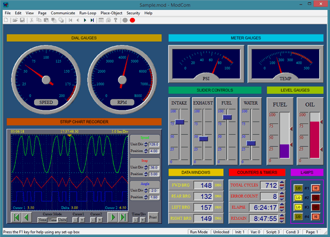
If using our ModCom HMI software, the carriage return is not necessary because ModCom automatically inserts this at the end of each command string. ModCom has a communications dialog box which can be used to transmit individual commands to the DAQ modules and see the data coming back. This is helpful in learning the style of the
Voltage Output & Ramping
Each output channel of the Analog Output DAQ units emit a control voltage which is dictated by the host that can be used to control equipment or machinery that accepts a ±10V control signal. ANote, these outputs do not deliver enough current to directly drive a load. If wishing to control the current driven thru a load, use the PWM output of a Digital Output unit instead which can deliver up to one full amp.

